analog filter design ppt
An exception would be notch lters 821 Symmetric and antisymmetric FIR lters I focus on the symmetric case. Frame 2 Slide 2 A.
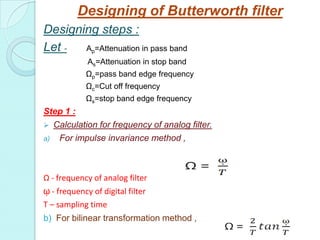
Butterworth Filter Design
It is relatively easy to design a frequency filtering circuit with an operational amplifier op amp that can handle signals that have frequencies between 001 Hz and 100 kHz Smith.
. Design and implement IIR filters using frequency transform and bilinear transform. 11 General Types of Filters Filter types are defined based on how they modify the magnitude andor phase of sinusoidal. A notch filter is a band-stop filter with a narrow stop band high Q factor.
On the other hand Class II materials like X7R and X5R feature mid-range stability as well as K value while offering much higher capacitance values. APPROXIMATIONS FOR ANALOG FILTERS 101 Introduction 102 Realizability 103 to 107 Butterworth Chebyshev Inverse-Chebyshev Elliptic and Bessel-Thomson Approximations. The characteristics of analog filter circuits particularly those containing active components are subject to drift and are dependent on temperature.
Other titles in the EDN Series for Design Engineers Electromagnetics Explained. Design active filters with real op amps in minutes. IIR filters can be design by pole-zero location Digital oscillators.
Filters may be classified as either digital or analog. An analog filter is the interconnection of components resistors capacitors inductors active devices It has one input excitation and one input response It determines a frequency selective transmission. This material is not forcommercialpurpose.
Four types of filters - Ideal lowpass highpass bandpass bandstop Background. Chapter 8 IIR Filter Design. 11 Filters and Signals.
Written for advanced undergraduate and first-year graduate courses in analog filter design and signal processing Design of Analog Filters integrates theory and practice to provide a modern and practical how-to approach to design. The basic concept of a filter can be explained by examining the frequency dependent nature of the impedance of capacitors and inductors. 2M 1 5 then M2.
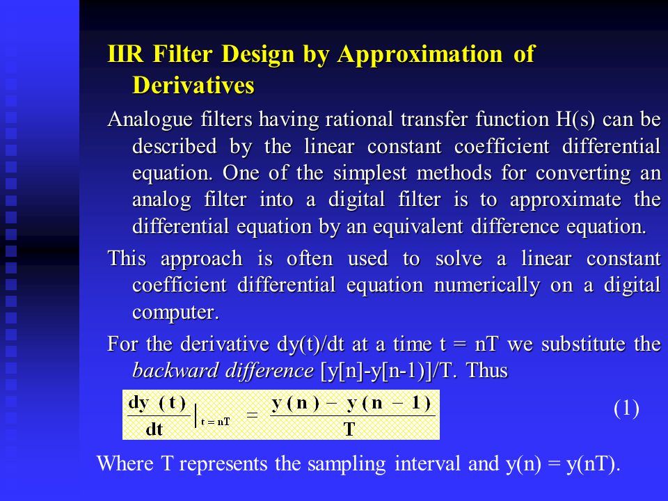
Digital filters are implemented using a digital computer or special purpose digital hardware. An analog filter may be described as. The shape of the response does not depends on the time of application of the.
Designing using Butterworth Approximation Design equation and design steps. An analog filter can only be changed by redesigning the filter circuit. Therefore for RF or analog circuit designer it is important to understand how to design and construct filters.
Band stop filter is a filter that passes most frequency but attenuates those in a specific range to very low levels. Every analog or radio frequency RF circuit performs filtering on the signals passing through them. Bandpass-filter design 40m band 13 While Class I dielectric materials such as C0G and U2J offer more temperature-stable dielectrics they have a lower dielectric constant K.
Analog filters also provide a greater dynamic range for frequency. We previously answered this in the pole-zero. From this pattern we can construct Ha s which is the system function of our analog filter.
Antoniou Digital Signal Processing Secs. Hz MX 1 n0 hnz n. What Does a.
A Handbook for Wireless RE EMC and High-speed Electronics by Ron Schmitt 0-7506-7403-2 Hardcover 359 pgs 3499 Practical RF Handbook Third Edition by Ian Hickman 0. ANALOG FILTERS SECTION 81. Summary of IIR Filter.
How do we make a lter have linear phase. Passive Analog Filters Background. Digital Signal Processing TT3313 Analog Filter Design - Techniques Reza Moheimani Practical.
Xt yt 5 Classification of Systems. Digital filters are easily designed tested and implemented on a general-purpose computer or workstation. INTRODUCTION Filters are networks that process signals in a frequency-dependent manner.
The methods do not lead to a simple closed form design formulas for discrete-time IIR case. Have relatively simple closed form design. Up to 24 cash back Analog Filter Design1 2 3 4 Slides are prepared to use in class room purpose may be used as a reference material All the slides are prepared based on the reference material Most of the gurescontent used in this material are redrawn some of the gurespictures are downloaded from the Internet.
Lowpass highpass bandpass bandstop Passive Analog Filters Digital Signal Processing Basics A basic DSP system is composed of. Poles on the unit circle Notch filters. An ADC providing digital samples of an analog input A Digital Processing system μPASICFPGA A DAC.
Zeros on the unit circle with nearby poles to control notch width Classic analog filters can be designed using the bilinear transformation IIR filters have the advantage of smaller filter order for a given frequency response. PowerPoint PPT presentation. It will not turn a novice into a filter de-signer but it can serve as a starting point for those wishing to learn more about filter design.
This Application Note is intended to serve as a very basic in-troduction to some of the fundamental concepts and terms associated with filters. Time-Invariant and Time-Varying. Analog filter is stable if.
In fact for FIR lter design we usually design hn directly rather than starting from a pole-zero plot. Design of Analog Filters. A digital filter in general is a computational process or algorithm that converts one sequence of numbers representing the input signal into another sequence representing the output signal.
A complete revision of Mac Van Valkenburgs classic work Analog Filter Design 1982 this text builds on the presentation and. Given Op Os Rp and As three parameters are required to. In our case we need to eliminate the mains hum which is an audible oscillation of AC at the frequency of the mains.
Let A pAttenuation in passband AsAttenuation in stop band ΩpPassband edge frequency ΩcCut off frequency ΩsStopband edge frequency In the problem the specifications of required digital filter is given and it will be asked to design a particular discrete time butterworth. K dielectric constant. Disadvantages Analog filters require physical space so they must be used sparingly if space is.
Determine the transfer function. Analog IIR filter design is highly advanced. Normalized cut-off frequencies.
Consider a voltage divider where the shunt leg is a reactive impedance. Analog Devices Uses Cookies for Enhanced Online Performance Some cookies are required for secure log-ins but others are optional for functional activities. View analog filter design - techniques 0207pptx from INFORMATIC 9 0954M at Telkom University Bandung.
T This presentation deals with the basics of these approximations. Lecture14m Frequency warping Given bilinear transformation and s j2pF Lets look at how freq in analog filters F can be translated to freq in digital filters f Learning through example Building a digital lowpass filter from Chebyshev-I given our. Design a 5-tap FIR band reject band-stop filter with a lower cut-off frequency of 2000 Hz an upper cut-off frequency of 2400 Hz and a sampling rate of 8000 Hz using the Hamming window method.